Working theory
The working theory of the flow measurement of the throttling device is based on the famous Bernoulli Hydrodynamic Theory. As shown in the below figure (1), if one throttling element is put in the pipeline, a Differential-pressure (Differential-pressure P) will be produced on both sides of the throttling element when there are liquids flowing through the throttling element, and the flow at this time is in proportion to the square root of the differential pressure, that’s to say,
Volume Flow: QV = A *C / √ (1-β4 ) * ε * d2 * √ (ΔP/ρ )
In the formula,
A----refers to the constants;
C---refers to the effluent coefficient;
β---refers to the diameter rate (=D/d);
d---refers to the hole caliber of the throttling element (mm);
ε---refers to the expansive coefficient;
ΔP--- refers to the Differential-pressure between the front and back of the throttling element (Pa);
ρ---refers to the density of the fluid in the working state (Kg/m3).
.png)
Figure (1) Measurement Theory of Throttling Devices
Technical Parameters
| Fluids |
Gas/Steam |
Liquid |
| Accuracy |
±1.5% |
±1.0% |
| Repeatability |
0.3% |
0.2% |
| Pipeline size |
DN80-DN2000 |
| Ratio Range |
≥10:1 |
| Operation Pressure |
≤42 Mpa |
| Fluids Temperature |
≤800℃ |
| straight Pipelines |
Upstream 7-24D,downstream 3-4D |



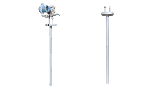


.png)
.png)
.png)
.png)
.png)
.png)
.png)
.png)
.png)
.png)
.png)
.png)