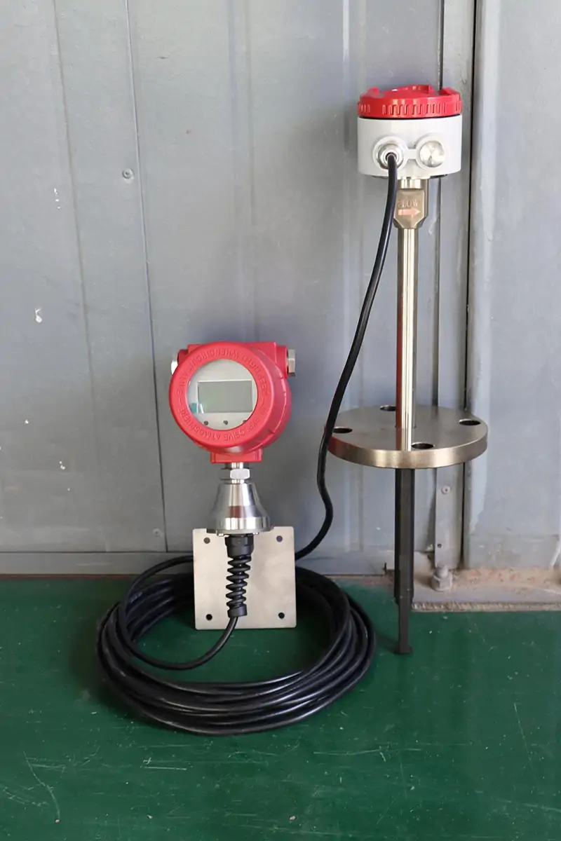
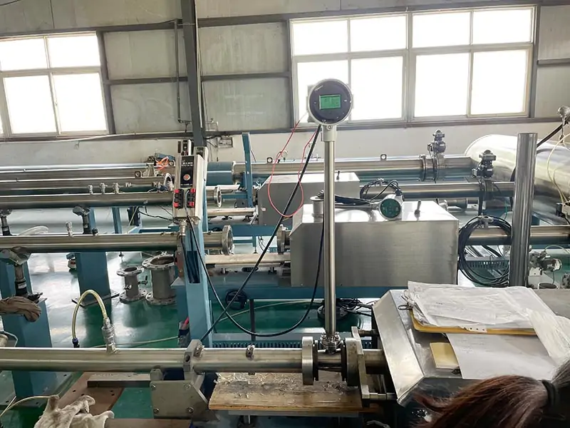
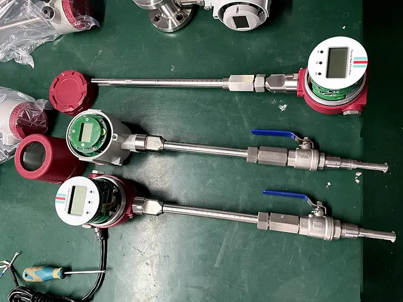
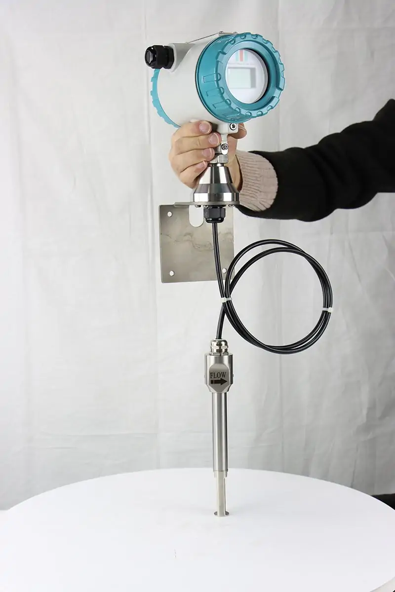
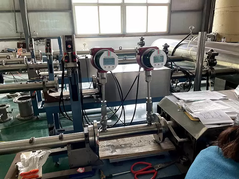
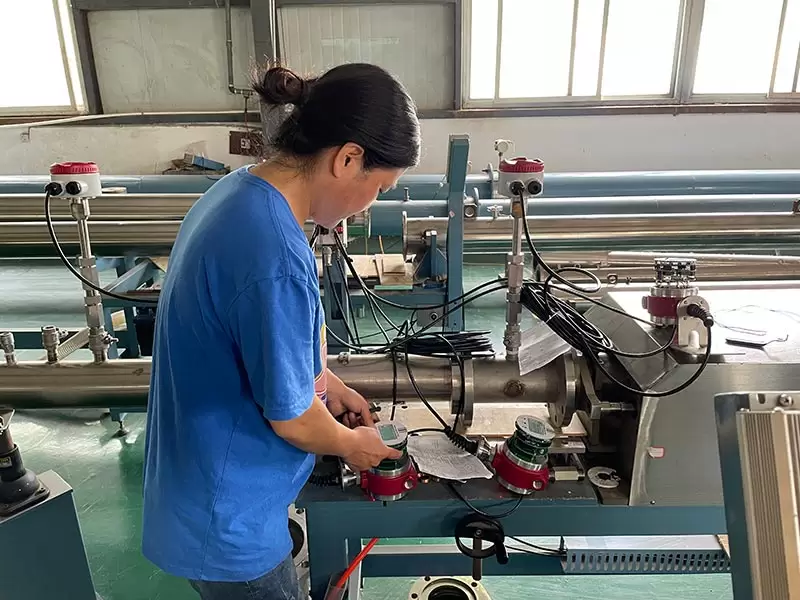
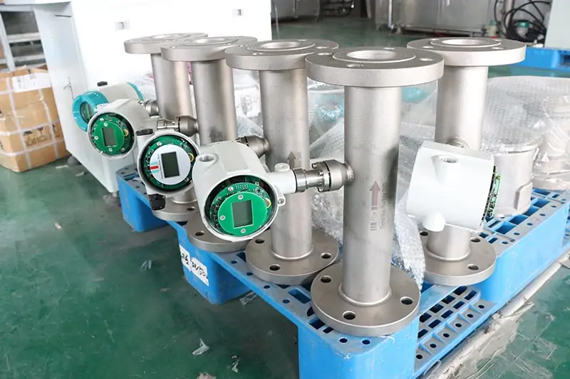
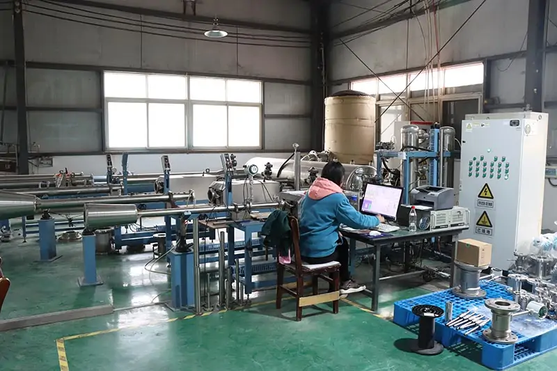
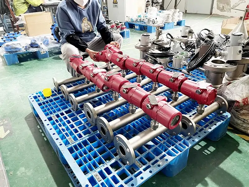
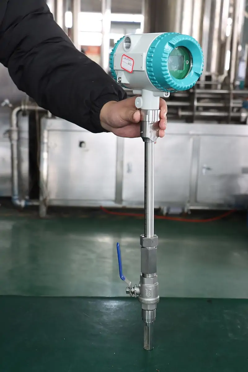
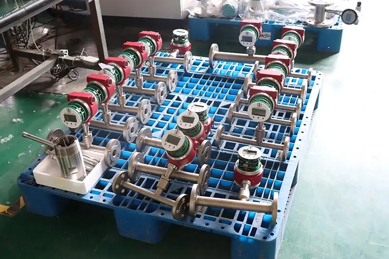
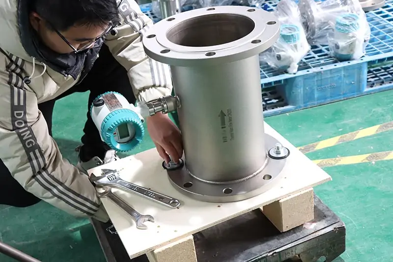
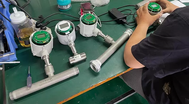
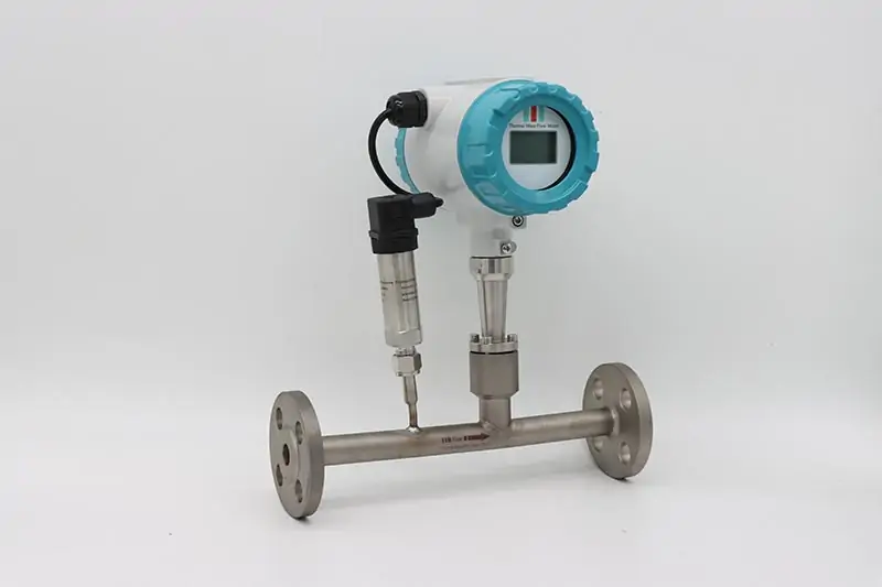
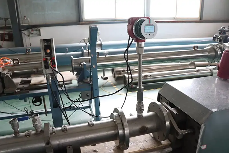
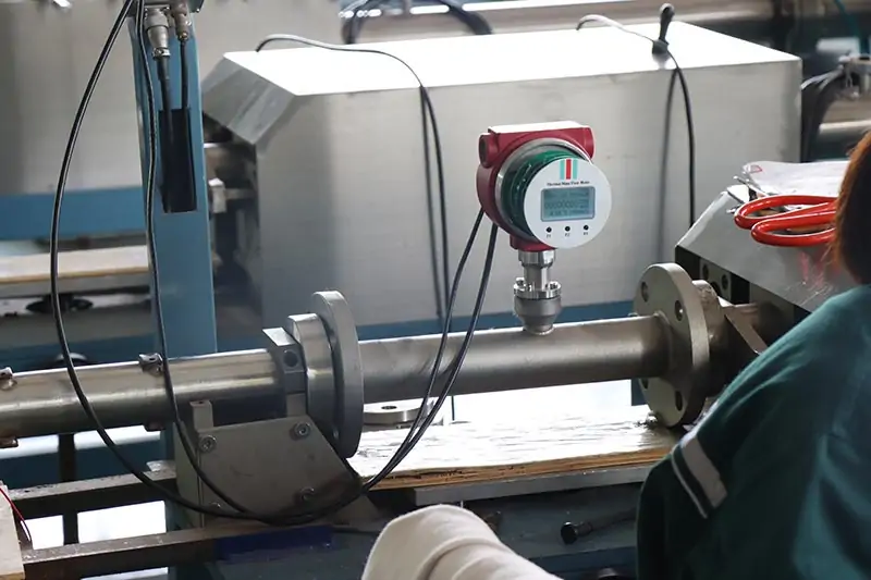
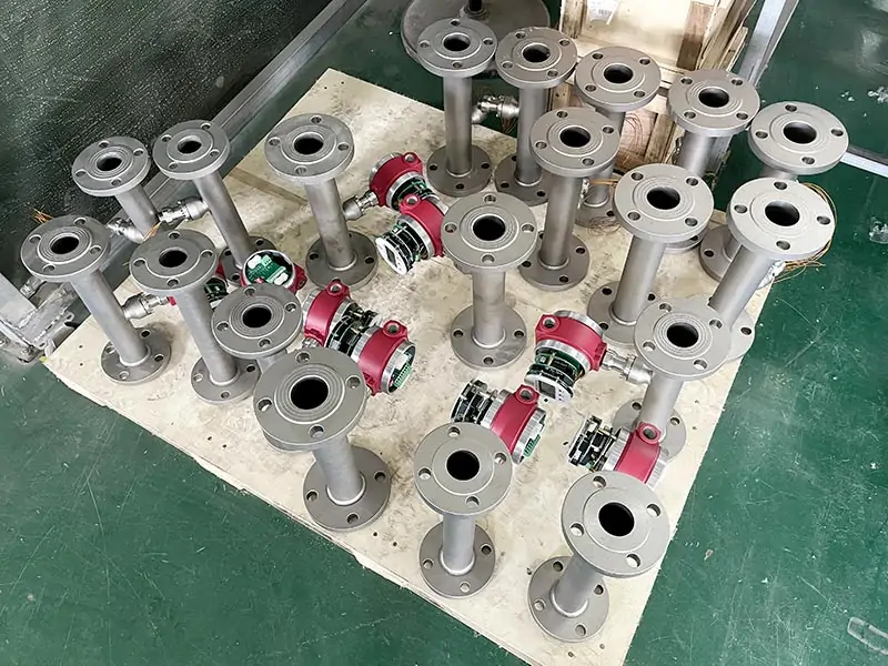
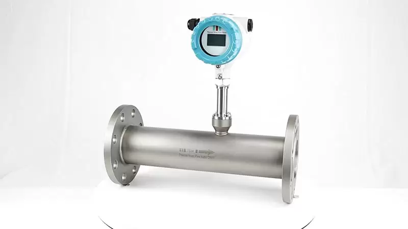
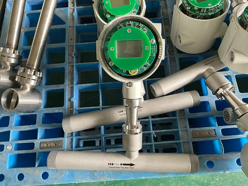
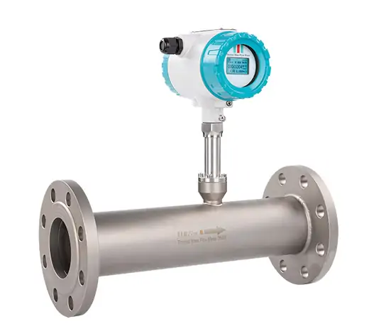
SS304 flange thermal dry gas mass flow meter
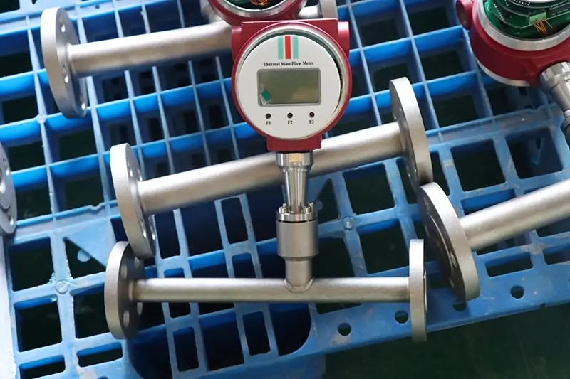
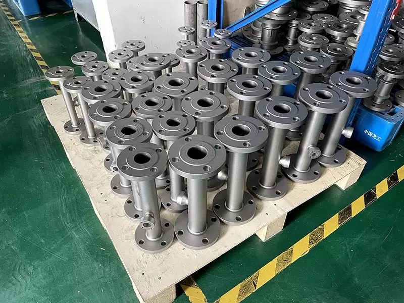
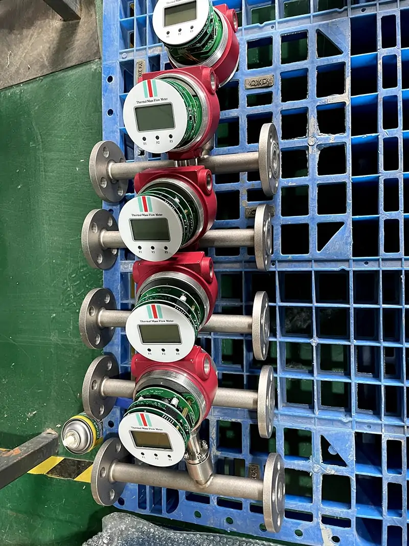
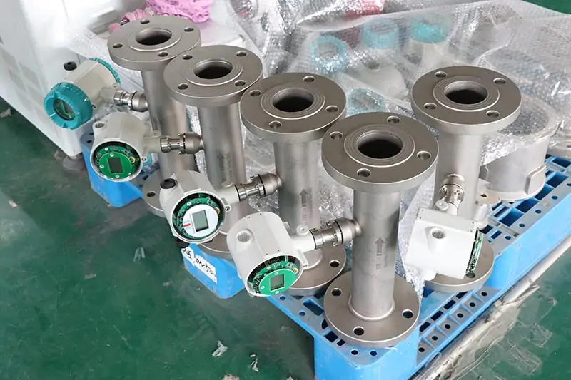
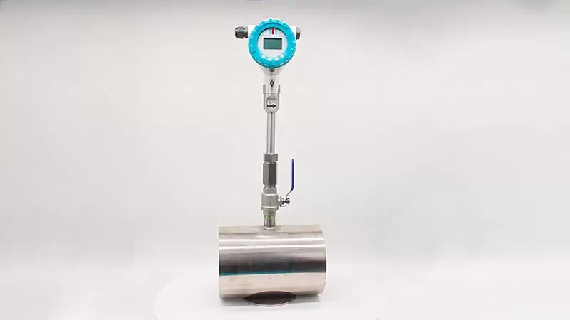
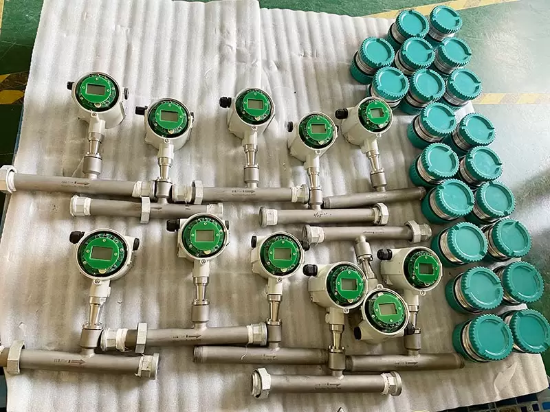
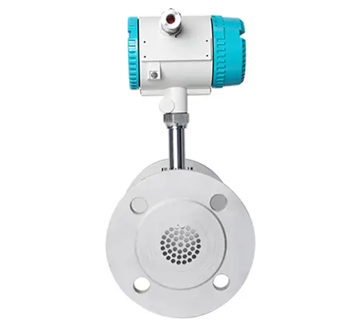
Thermal dry gas flow meter is mainly used in air and gas flow measurement. The meters have flange type,wafer type,thread type,tri-clamp type;
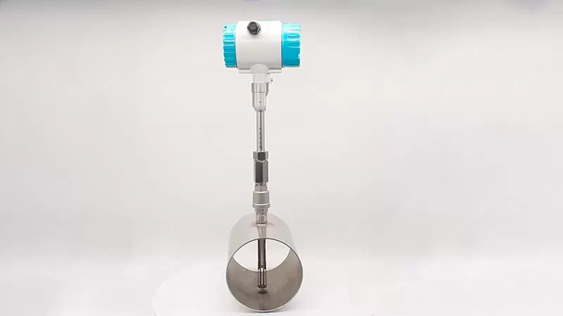
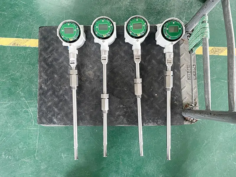
Thermal gas mass flow meter consist of a transmitter and probe with temperature sensors (RTDS) located in the pins at the bottom of the probe. One sensor measures the process temperature and the other sensor is heated to a specific temperature above this. As the flow rate increases, heat gets taken away from the heated sensor in the form of convective heat transfer.
Media temperature:-40~+220¡æ
Size£º
Insertion type:DN32~DN4000
Flange type:DN10~DN300
Tri-clamp type :DN10~DN100
Thread type:DN10~DN100
Accuracy:
In-line type accuracy:¡À1.0%
Insertion type accuracy::¡À1.5%
Introduction
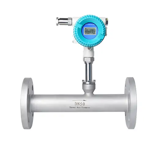
Flange thermal gas mass flow meter is one of kind mass flow meter which is popular in industrial applications is the way they are designed and built. The feature is no moving parts, nearly unobstructed straight through flow path, require no temperature or pressure corrections and retain accuracy over a wide range of flow rates. Straight pipe runs can be reduced by using dual-plate flow conditioning elements and installation is very simple with minimal pipe intrusions.
Flange thermal gas mass flow meter size from DN10~DN2000mm
 |
 |
 |
https://www.qtmeters.com/products/thermal-mass-flow-meter/
Advantages
Flange thermal gas mass flow meter advantanges :
(1)Wide range ratio 1000:1;
(2)Large diameter, low flow rate, negligible pressure loss;
(3)Direct mass flow measurement without temperature and pressure compensation;
(4)Very sensitive for low flow rate measurement;
(5)Easy to design and select, easy to install and use;
(6)Suitable for all kinds of single or mixed gas flow measurement Could measure gas with flow velocity from 100Nm/s to 0.1Nm/s, which can be used for gas leak detection;
(7) The sensor has no moving parts and pressure sensing parts, and is not affected by vibration on the measurement accuracy. It has good seismic performance and high measurement reliability;
(8) No pressure loss or very small pressure loss.
(9) When measuring the gas flow, it is often expressed in the volume flow unit under the standard state, and the medium temperature/pressure change hardly affects the measured value. If the density is constant in the standard state (that is, the composition is unchanged), it is similar to a mass flow meter;
(10) Support multiple communication methods, such as RS485 communication, MODBUS protocol, etc., which can realize factory automation and integration
Technical Data
Table 1: Flange Thermal Gas Mass Flow Meter Parameter
| Measuring Medium | Various of Gas (Except acetylene) |
| Pipe Size | (Insert connection) DN50-DN2000mm ,In-line connection(DN10-DN2000mm) |
| Velocity | 0.1-100Nm/s |
| Accuracy | +/-1~2.5% |
| Working Temperature | Sensor:-40~+220 degC Transmitter:-20~+45 degC |
| Working Pressure | Insertion Sensor:medium pressure ≤1.6Mpa
Flanged Sensor:medium pressure ≤4.0Mpa Special pressure please double check |
| Power Supply | Compact type: 24VDC or 220VAC, Power consumption ≤18W
Remote type:220VAC,Power consumption ≤19W |
| Response Time | 1s |
| Output | 4-20mA(optoelectronic isolation,maximum load 500Ω),Pulse RS485(optoelectronic isolation) and HART |
| Alarm Output | 1-2 line Relay, Normally Open state, 10A/220V/AC or 5A/30V/DC |
| Sensor Type | Standard Insertion, Hot-tapped Insertion and Flanged |
| Construction | Compact and Remote |
| Pipe Material | Carbon Steel, Stainless Steel,Plastic etc. |
| Display | 4 lines LCD Mass flow, Volume flow in standard condition, Flow totalizer, Date and Time, Working time, and Velocity, etc. |
| Protection | IP65 |
Table 2: Flange Thermal Gas Mass Flow Meter Sizing
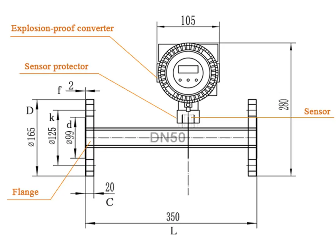
| Nominal Diameter | Flange outer diameter | Center hole | Bolt hole | Screw Threads | Sealing face | Flange thickness | Installation length | |
| DN | D | k | n x L | d | f | C | L | |
| 15 | 95 | 65 | 4×14 | M12 | 46 | 2 | 14 | 280 |
| 20 | 105 | 75 | 4×14 | M12 | 56 | 2 | 16 | 280 |
| 25 | 115 | 85 | 4×14 | M12 | 65 | 2 | 16 | 280 |
| 32 | 140 | 100 | 4×18 | M16 | 76 | 2 | 18 | 350 |
| 40 | 150 | 110 | 4×18 | M16 | 84 | 2 | 18 | 350 |
| 50 | 165 | 125 | 4×18 | M16 | 99 | 2 | 20 | 350 |
| 65 | 185 | 145 | 4×18 | M16 | 118 | 2 | 20 | 400 |
| 80 | 200 | 160 | 8×18 | M16 | 132 | 2 | 20 | 400 |
| 100 | 220 | 180 | 8×18 | M16 | 156 | 2 | 22 | 500 |
Table 3: Common Use Gas Maximum Range
| Caliber
( mm ) |
Air | Nitrogen ( N2 ) | Oxygen ( O2 ) | Hydrogen ( H2 ) |
| 15 | 65 | 65 | 32 | 10 |
| 25 | 175 | 175 | 89 | 28 |
| 32 | 290 | 290 | 144 | 45 |
| 40 | 450 | 450 | 226 | 70 |
| 50 | 700 | 700 | 352 | 110 |
| 65 | 1200 | 1200 | 600 | 185 |
| 80 | 1800 | 1800 | 900 | 280 |
| 100 | 2800 | 2800 | 1420 | 470 |
| 125 | 4400 | 4400 | 2210 | 700 |
| 150 | 6300 | 6300 | 3200 | 940 |
| 200 | 10000 | 10000 | 5650 | 1880 |
| 250 | 17000 | 17000 | 8830 | 2820 |
| 300 | 25000 | 25000 | 12720 | 4060 |
| 350 | 45000 | 45000 | 22608 | 5600 |
| 400 | 70000 | 70000 | 35325 | 7200 |
| 450 | 100000 | 100000 | 50638 | 9200 |
| 500 | 135000 | 135000 | 69240 | 11280 |
| 600 | 180000 | 180000 | 90432 | 16300 |
| 700 | 220000 | 220000 | 114500 | 22100 |
| 800 | 280000 | 280000 | 141300 | 29000 |
| 900 | 400000 | 400000 | 203480 | 36500 |
| 1000 | 600000 | 600000 | 318000 | 45000 |
| 2000 | 700000 | 700000 | 565200 | 18500 |

